Hybrid Power Managers
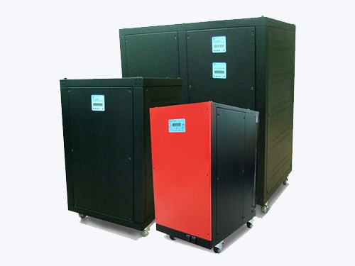

An effective hybrid power management solution monitors, manages and controls available electric energy sources. Our Hybrid Power Manager (HPM) family features products that are second to none in delivering operational stability of the power infrastructure. HPMs have fully selectable and automated real-time power management modes. Each HPM model balances storage capabilities and output requirements, in a sophisticated, yet user friendly situational management system.
System Overview
Our Hybrid Power Manager (HPM) fully integrates smart energy storage and automated power management capabilities in a 24/7 self-sustaining power plant. HPMs are available in 12 kWh to 2 MWh battery storage and 10 KVA to 350 KVA Input / Output Systems.
Features:
- Global Availability (Single Phase / Split Phase / Tri-Phase)
- Multiple Source Inputs for Solar, Wind and Grid
- High Speed Charging Capabilities
- Fan-less Silent Operations
- Maintenance Free Operations
Operational Capabilities:
- Peak Shaving / Load Leveling / Time-of-Use (TOU)
- Power Regulating
- Emergency Back-UP
Components:
- High Voltage Lithium-Ion Battery Pack
- True Sine Wave Inverter
- Charger System with Multiple Solar Array, Wind and Grid Sources
- ‘All-in-One’ Battery and Power Management LCD Control Panel
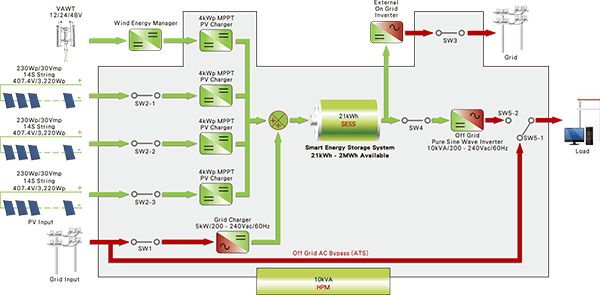
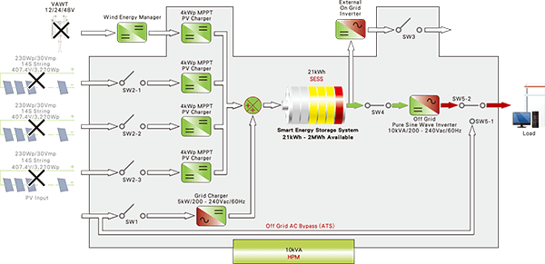
HPM Architecture Design:
The HPM design allows a variety of selectable modes to function as a UPS System during power outages or a Peak Shaving Device to take advantage of local utility rates / TOU programs. The following HPM Architecture Design displays components and their use to store energy and optimize the use of available power:
Our HPMs are fully CEC / IEC certified to the following standards:
- IEC 62109-1
- IEC 62109-2
- IEC 62019-1
- IEC 62040-1
- IEC 62040-2
- IEC 61000-6-2
- IEC 61000-6-3
- IEC 50178
HPM System Modes
Our HPMs offer 5 different system settings that can adjust to a variety of client requirements:
- UPS Mode
- Charge Mode
- ON Grid Mode
- OFF Grid 1 Mode
- OFF Grid 2 Mode
The UPS Mode is the default mode for any situation where the system is not connected with the Grid. In cases when the Grid is connected, the other four modes become available. Each HPM System Mode can be programmed to optimize renewable energy use, as required.
UPS Mode
Condition of battery discharging to loads when the Grid is not available:
| Mode | Description | Condition |
|---|---|---|
| Mode1: ON | Function at all times. | Battery Voltage:
|
| Mode2: OFF | Does NOT function | |
| Mode3: PROG | Function periodically. | Battery Voltage:
|
Charge Mode
Condition of Grid charging battery:
| Mode | Description | Condition |
|---|---|---|
| Mode1: ON | Function at all times. | Battery Voltage:
|
| Mode2: OFF | Does NOT function | |
| Mode3: PROG | Function periodically. | Battery Voltage:
|
ON Grid Mode
Condition of battery discharging to feed the Grid when the Grid is available:
| Mode | Description | Condition |
|---|---|---|
| Mode1: ON | Function at all times. | Battery Voltage:
|
| Mode2: OFF | Does NOT function | |
| Mode3: PROG | Function periodically. | Battery Voltage:
|
OFF Grid 1 Mode & OFF Grid 2 Mode
Condition of battery discharging to loads when the Grid is available:
| Mode | Description | Condition |
|---|---|---|
| Mode1: ON | Function at all times. | Battery Voltage:
|
| Mode2: OFF | Does NOT function | |
| Mode3: PROG | Function periodically. | Battery Voltage:
|
Please note the OFF Grid 1 Mode and OFF Grid 2 Mode simply offer two separate timers for the day. These modes will not conflict with each other if settings overlap.
PV / VAWT Charging Conditions
Photovoltaic and / or Wind Turbine charging are not affected by various mode settings; however, charging is activated when the following two conditions are achieved:
| Condition | Voltage | Status | |
|---|---|---|---|
| 1 |
|
> 170V ~ 500V | start charging |
| < 150V | stop charging | ||
| 2 |
|
> 420V | stop charging |
| < 405V | start charging | ||
Interactions between HPM Modes
Interactions are limited to certain combinations, bearing in mind that the order of precedence is set to: Charge Mode Eƒ OFF Grid 1 Mode / Off Grid 2 Mode Eƒ ON Grid Mode
HPM Architecture Design used in Operational Settings
Using the various HPM Modes in specific operational settings, we display 22 configurations of their use below:
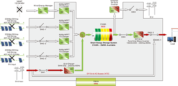
1. UPS Mode (PV or VAWT Not Installed)
Charging
- Grid Works
- Battery NOT full
- Grid supplies load (ATS bypass)

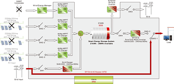
2. UPS Mode (PV or VAWT Not Installed)
Charging
- Grid Works
- Battery full
- Grid supplies load (ATS bypass)

3. UPS Mode (PV or VAWT Not Installed)
UPS Supply
- Grid out
- Battery discharging to load until 10% (definable) capacity

4. UPS Mode and Power Saving Mode (PV or VAWT Not Installed)
Grid charging in OFF PEAK HOURS (e.g.0000 Hrs. to 0600 Hrs.)
- Grid works
- Battery NOT full
- Grid supplies load (ATS bypass)

5. UPS Mode and Power Saving Mode (PV or VAWT Not Installed)
ECO discharging in PEAK-HOURS (e.g.0700 Hrs. to 0900 Hrs. & 1700 Hrs. to 2100 Hrs.)
- Grid works
- Battery full
- Battery discharges to load until 20% (definable) capacity

6. UPS Mode and Power Saving Mode (PV or VAWT Not Installed)
Grid supply
- Battery out
- Grid supplies load (ATS bypass)
- Battery waiting for off-peak grid charging

7. UPS Mode and Power Saving Mode (PV or VAWT Not Installed)
UPS supply
- Grid out
- Battery discharges to load until 10% capacity

8. Pure Island On-Line UPS (Grid NOT available)
On-Line PV and VAWT charging
- Grid NOT available
- PV charges battery
- Battery supplies load
- Grid in standby
- Solar / Wind charge battery
- Battery discharges load

9. Pure Island On-Line UPS (Grid NOT available)
On-Line discharging
- PV / Wind out
- Battery supplies load until 10% (definable) capacity
10. On-Line OFF Grid Home Power Plant Mode (Grid available)
On-Line charging and discharging
- Grid charges
- Solar / Wind charge
- Battery discharges to load
- Battery discharges to load

11. On-Line OFF Grid Home Power Plant Mode (Grid available)
On-Line UPS Mode
- Grid out
- Solar / Wind work
- Battery discharges to load until 10% (definable) capacity

12. On-Line OFF Grid Home Power Plant Mode (Grid available)
On-Line charging and discharging
- Grid charges
- Solar / Wind out
- Grid standby
13. On-Line OFF Grid Home Power Plant Mode (Grid available)
On-Line UPS Mode
- Grid out
- Solar / Wind work
- Battery discharges to load until 10% (definable) capacity

14. Off-Line OFF Grid Home Power Plant Mode (Grid available)
Off-Line ECO Hybrid charging
- Grid charges in peak hours
- Solar / Wind charge
- Battery not full
- Grid supplies load (ATS bypass)

15. Off-Line OFF Grid Home Power Plant Mode (Grid available)
ECO discharging in PEAK HOURS (e.g. 0700 Hrs – 0900 Hrs.)
- Grid works
- Solar / Wind work or out
- Battery discharges to load until 10% (definable) capacity

16. Off-Line OFF Grid Home Power Plant Mode (Grid available)
Grid supply
- Solar / Wind out
- Battery out
- Grid supplies load (ATS bypass)

17. Off-Line OFF Grid Home Power Plant Mode (Grid available)
UPS supply
- Grid out
- Solar / Wind out
- Battery discharges to load until 10% (definable) capacity

18. On-Line ON Grid Home Power Plant Mode
Off-line charging
- Grid works
- Solar / Wind charge batteries
- Battery not full
- Grid supplies load (ATS bypass)

19. On-Line ON Grid Home Power Plant Mode
On Grid discharging
- Grid works
- Solar / Wind work
- Battery discharges to external inverter from full until 10% (definable) capacity

20. On-Line ON Grid Home Power Plant Mode
UPS supply
- Grid out
- Solar / Wind work
- Battery discharges to load until 10% (definable) capacity

21. On-Line ON Grid Home Power Plant Mode
Grid supply
- Grid works
- Solar / Wind out
- Battery out
- Grid supplies load (ATS bypass)
22. UPS Mode (PV / VAWT not installed)
Grid supply
- Grid works
- Battery not full
- Grid supplies load (ATS bypass)

Specifications
We offer Commercial-Off-The-Shelf (COTS) products for single, split phase and tri-phase service. Our HPM products can also be custom designed to meet client requirements. We can service utility customers, microgrid generation systems and utilities alike. Please ensure you call upon us early in your project planning so we can team up to really optimize your hybrid power management Architecture Design.
Individual HPM specifications are detailed in the sub-menu above.
Selecting your HPM
The size of a HPM is based on the amount of power and the level of autonomy a client requires.
Solar, Wind and HPM Package
To start, we really focus on the power requirements of a home or facility and the level of autonomy desired in hours or days, then we can build a renewable/grid architecture. A client’s renewable preferences and available or required grid support will drive the architecture in terms of the mix between renewable and grid contribution. It is important to note, the client’s renewable contribution is based on which part of the world / specific location the system will be installed. For example, 1kW of Solar in Jamaica provides approximately 2450 kWh per year. That same amount of Solar in the northeast US will only provide 1200 kWh per year. If renewable energy includes Vertical Axis Wind Turbines (VAWTs), their output per kW will typically deliver 4380 kWh per year. Once we have established the expected renewable energy generation capability in terms of what the client wants and can afford, then we turn our attention to which Hybrid Power Manager (HPM) system will best meet that client’s operational needs.
HPM Matching
For clients that already have a renewable and/or grid mix and simply want to match an HPM, our entire focus is on how much energy is currently being produced or available and just how much autonomy the client wants.
Electrical Service
The electrical service required will impact the specific HPM model selection, i.e. voltage level, phase, hertz, etc.
Microgrids and Utility Infrastructure
For larger systems, we typically favor multiple stings of renewable systems and multiple HPMs to ensure redundancy and maintain very high levels of reliability of available power.
HPM 1210

HPM 1210 – 12 kWh Smart Energy Storage System Specifications
| Item | Specification |
|---|---|
| Battery Type | Li-Ion |
| Voltage | 400V |
| Nominal Capacity | 30Ah |
| Cycle Life |
|
| Max Charge Current | 36A |
| Nominal Charge Current | 30A |
| Max Discharge Current | 25A |
| Continuous Discharge Current | 20A |
| Internal Resistance | ≦ 10μ Ω |
| Charge Method | CC / CV |
| Battery Charge Voltage | 420V ± 0.5V |
| Battery Charge Cut Off Voltage | 430V |
| Battery Protection | OVP / UVP / OCP / OTP |
| Consumption | Standby < 1W, No Load < 10W |
| Status Indication | LED |
| Operating Temperature Range | -35 ~ +60℃ |
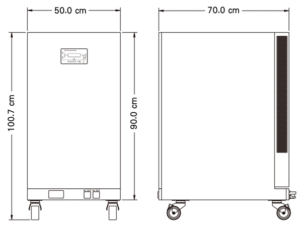
| Dimensions (H×D×W) | 100.7cm x 50cm x 70cm |
| Weight | 200kg |
| Water & Dust Proof Level | Indoor Type (IP65/67/68 Available) |
HPM 1210 Dimensions
HPM 1210 – 10 KVA Hybrid Power Manager Specifications
| Item | Specification | ||
|---|---|---|---|
| Model | HEM-10kVA | ||
| Independent Off Grid Output (Inverter) | AC Output | Continuous Output Power in FTS | 10kVA |
| Surge Output Power (L-L) |
|
||
| Nominal Output Voltage (AC) |
|
||
| Nominal Output Current (L-L) | 34A | ||
| Max Output Current (Instant L-L) | 54A | ||
| On Grid Output | DC Output | Nominal Output Voltage (DC) | 400Vdc |
| Nominal Output Current (DC) | 15A | ||
| Nominal Output Power (DC) | 5000W | ||
| Grid Charger | AC Input | Nominal Input Voltage (AC) | 200~240Vac |
| Nominal Input Current | 25A | ||
| Max Input Current (Instant) | 28A | ||
| Nominal Input Power (AC) | 5000W | ||
| PV Charger | DC (PV)Input | Input Type | PV *4 |
| Input Voltage Range | 170~500Vdc | ||
| Nominal Input Voltage | 400Vdc | ||
| Max Input Voltage | 500Vdc | ||
| Nominal Input Current | 10A *4 | ||
| Max Input Current (Instant) | 12A *4 | ||
| General | Operating Temperature | -35~+60℃ | |
| Max Internal Temperature |
|
||
| Battery Protection | OVP / UVP / OCP / OTP | ||
| Consumption |
|
||
| Status Indication | Central LCD | ||
HPM 1210 Placement and Clearance Requirements

HPM 1610
HPM 1610 – 16 kWh Smart Energy Storage System Specifications
| Item | Specification |
|---|---|
| Battery Type | Li-Ion |
| Voltage | 400V |
| Nominal Capacity | 40Ah |
| Cycle Life |
|
| Max Charge Current | 36A |
| Nominal Charge Current | 30A |
| Max Discharge Current | 30A |
| Continuous Discharge Current | 25A |
| Internal Resistance | ≦ 10μ Ω |
| Charge Method | CC / CV |
| Battery Charge Voltage | 423V ± 0.5V |
| Battery Charge Cut Off Voltage | 470V |
| Battery Protection | OVP / UVP / OCP / OTP |
| Consumption | Standby < 1W, No Load < 10W |
| Status Indication | LED |
| Operating Temperature Range | -35 ~ +60℃ |
| Dimensions (H×D×W) | 100.7cm x 50cm x 70cm |
| Weight | 175kg |
| Water & Dust Proof Level | Indoor Type (IP65/67/68 Available) |
HPM 1610 Dimensions
HPM 1610 – 10 KVA Hybrid Power Manager Specifications
| Item | Specification | ||
|---|---|---|---|
| Model | HEM-10kVA-SP | ||
| Independent Off Grid Output (Inverter) | AC Output | Continuous Output Power in FTS | 10kVA |
| Surge Output Power (L-L) |
|
||
| Nominal Output Voltage (AC) |
|
||
| Nominal Output Current (L-L) | 34A | ||
| Max Output Current (Instant L-L) | 54A | ||
| On Grid Output | DC Output | Nominal Output Voltage (DC) | 400Vdc |
| Nominal Output Current (DC) | 15A | ||
| Nominal Output Power (DC) | 5000W | ||
| Grid Charger | AC Input | Nominal Input Voltage (AC) | 200~240Vac |
| Nominal Input Current | 25A | ||
| Max Input Current (Instant) | 28A | ||
| Nominal Input Power (AC) | 5000W | ||
| PV Charger | DC (PV)Input | Input Type | PV *4 |
| Input Voltage Range | 170~500Vdc | ||
| Nominal Input Voltage | 400Vdc | ||
| Max Input Voltage | 500Vdc | ||
| Nominal Input Current | 10A *4 | ||
| Max Input Current (Instant) | 12A *4 | ||
| General | Operating Temperature | -35~+60℃ | |
| Max Internal Temperature |
|
||
| Battery Protection | OVP / UVP / OCP / OTP | ||
| Consumption |
|
||
| Status Indication | Central LCD | ||
HPM 1610 Placement and Clearance Requirements
HPM 2810
HPM 2810 – 28 kWh Smart Energy Storage System Specifications
| Item | Specification |
|---|---|
| Battery Type | Li-Ion |
| Voltage | 400V |
| Nominal Capacity | 70Ah |
| Cycle Life |
|
| Max Charge Current | 36A |
| Nominal Charge Current | 30A |
| Max Discharge Current | 30A |
| Continuous Discharge Current | 25A |
| Internal Resistance | ≦ 10μ Ω |
| Charge Method | CC / CV |
| Battery Charge Voltage | 432V ± 0.5V |
| Battery Charge Cut Off Voltage | 470V |
| Battery Protection | OVP / UVP / OCP / OTP |
| Consumption | Standby < 1W, No Load < 10W |
| Status Indication | LED |
| Operating Temperature Range | -35 ~ +60℃ |
| Dimensions (H×D×W) | 100.7cm x 50cm x 70cm |
| Weight | 395kg |
| Water & Dust Proof Level | Indoor Type (IP65/67/68 Available) |
HPM 2810 Dimensions
HPM 2810 – 10 KVA Hybrid Power Manager Specifications
| Item | Specification | ||
|---|---|---|---|
| Model | HEM-10kVA-SP | ||
| Independent Off Grid Output (Inverter) | AC Output | Continuous Output Power in FTS | 10kVA |
| Surge Output Power (L-L) |
|
||
| Nominal Output Voltage (AC) |
|
||
| Nominal Output Current (L-L) | 34A | ||
| Max Output Current (Instant L-L) | 54A | ||
| On Grid Output | DC Output | Nominal Output Voltage (DC) | 400Vdc |
| Nominal Output Current (DC) | 15A | ||
| Nominal Output Power (DC) | 5000W | ||
| Grid Charger | AC Input | Nominal Input Voltage (AC) | 200~240Vac |
| Nominal Input Current | 25A | ||
| Max Input Current (Instant) | 28A | ||
| Nominal Input Power (AC) | 5000W | ||
| PV Charger | DC (PV)Input | Input Type | PV *4 |
| Input Voltage Range | 170~500Vdc | ||
| Nominal Input Voltage | 400Vdc | ||
| Max Input Voltage | 500Vdc | ||
| Nominal Input Current | 10A *4 | ||
| Max Input Current (Instant) | 12A *4 | ||
| General | Operating Temperature | -35~+60℃ | |
| Max Internal Temperature |
|
||
| Battery Protection | OVP / UVP / OCP / OTP | ||
| Consumption |
|
||
| Status Indication | Central LCD | ||
HPM 2810 Placement and Clearance Requirements
HPM 6030

HPM 6030 – 60 kWh Smart Energy Storage System Specifications
| Item | Specification |
|---|---|
| Battery Type | Li-Ion |
| Voltage | 400V |
| Nominal Capacity | 150Ah |
| Cycle Life |
|
| Max Charge Current | 70A |
| Nominal Charge Current | 60A |
| Max Discharge Current | 70A |
| Continuous Discharge Current | 60A |
| Internal Resistance | ≦ 10μ Ω |
| Charge Method | CC / CV |
| Battery Charge Voltage | 432V ± 0.5V |
| Battery Charge Cut Off Voltage | 500V |
| Battery Protection | OVP / UVP / OCP / OTP |
| Consumption | Standby < 1W, No Load < 10W |
| Status Indication | LED |
| Operating Temperature Range | -35 ~ +60℃ |
| Dimensions (H×D×W) | 119.2cm x 110cm x 64.8cm |
| Weight | 600kg |
| Water & Dust Proof Level | Indoor |
HPM 6030 Dimensions

HPM 6030 – 30 KVA 3 Phase Hybrid Power Manager Specifications
| Item | Specification | ||
|---|---|---|---|
| Model | INV-30KVA-3P | ||
| Independent Off Grid Output (Inverter) | AC Output | Continuous Output Power in FTS | 30kVA |
| Surge Output Power (L-L) |
|
||
| Nominal Output Voltage (AC) |
|
||
| Nominal Output Current (L-L) | 70A | ||
| Max Output Current (Instant L-L) | 150A | ||
| Grid Charger (Optional) | AC Input | Nominal Output Voltage (AC) | 415Vac |
| Nominal Output Current | 12A | ||
| Max Input Current Instant (Instant) | 15A | ||
| Nominal Output Power (AC) | 5000W | ||
| PV & Wind Charger | DC Input | Charging Capacity | 4kWp per MPPT |
| Input Type | MPPT * 8 (PV * 4 / Wind * 4) | ||
| Input Voltage Range | 170~500Vdc | ||
| Nominal Input Voltage | 400Vdc | ||
| Max Input Voltage | 500Vdc | ||
| Nominal Input Current | 10A *8 | ||
| Max Input Current (Instant) | 12A *8 | ||
| General | Operating Temperature | -35~+60℃ | |
| Max Internal Temperature |
|
||
| Battery Protection | OVP / UVP / OCP / OTP | ||
| Consumption |
|
||
| Status Indication | Central LCM | ||
HPM 6030 Placement and Clearance Requirements

HPM 12060
HPM 12060 – 120 kWh Smart Energy Storage System Specifications
| Item | Specification |
|---|---|
| Battery Type | Li-Ion |
| Voltage | 400V |
| Nominal Capacity | 150Ah |
| Cycle Life |
|
| Max Charge Current | 70A |
| Nominal Charge Current | 60A |
| Max Discharge Current | 70A |
| Continuous Discharge Current | 60A |
| Internal Resistance | ≦ 10μ Ω |
| Charge Method | CC / CV |
| Battery Charge Voltage | 432V ± 0.5V |
| Battery Charge Cut Off Voltage | 500V |
| Battery Protection | OVP / UVP / OCP / OTP |
| Consumption | Standby < 1W, No Load < 10W |
| Status Indication | LED |
| Operating Temperature Range | -35 ~ +60℃ |
| Dimensions (H×D×W) | 119.2cm x 110cm x 64.8cm |
| Weight | 600kg |
| Water & Dust Proof Level | Indoor |
HPM 12060 Dimensions
HPM 12060 – 60 KVA 3 Phase Hybrid Power Manager Specifications
| Item | Specification | ||
|---|---|---|---|
| Model | INV-60KVA-3P | ||
| Independent Off Grid Output (Inverter) | AC Output | Continuous Output Power in FTS | 60kVA |
| Surge Output Power (L-L) |
|
||
| Nominal Output Voltage (AC) |
|
||
| Nominal Output Current (L-L) | 140A | ||
| Max Output Current (Instant L-L) | 260A | ||
| Grid Charger (Optional) | AC Input | Nominal Output Voltage (AC) | 415Vac |
| Nominal Output Current | 12A | ||
| Max Input Current Instant (Instant) | 15A | ||
| Nominal Output Power (AC) | 5000W | ||
| PV & Wind Charger | DC Input | Charging Capacity | 4kWp per MPPT |
| Input Type | MPPT * 16 (PV * 8 / Wind * 8) | ||
| Input Voltage Range | 170~500Vdc | ||
| Nominal Input Voltage | 400Vdc | ||
| Max Input Voltage | 500Vdc | ||
| Nominal Input Current | 10A *16 | ||
| Max Input Current (Instant) | 12A *16 | ||
| General | Operating Temperature | -35~+60℃ | |
| Max Internal Temperature |
|
||
| Battery Protection | OVP / UVP / OCP / OTP | ||
| Consumption |
|
||
| Status Indication | Central LCM | ||
HPM 12060 Placement and Clearance Requirements